
Blog
Design for Manufacturability in Metal Casting: How to Optimize Part Design for Castability and Machinability
Meta Description: A comprehensive engineering guide to Design for Manufacturability (DFM) in metal casting and CNC machining. Learn how wall thickness, draft angles, fillets, machining allowance, and datum strategy affect casting yield, machining cost, and final part quality.
A casting drawing that looks perfect on screen can be impossible to produce on the foundry floor. The gap between CAD idealization and manufacturing reality is where cost overruns, delivery delays, and quality failures originate — and it is almost always traceable to design decisions made before the first pattern was cut.
Design for Manufacturability (DFM) in metal casting is the disciplined practice of designing a part so that it can be cast successfully, machined efficiently, and delivered at the target cost and quality. It is not about compromising engineering intent — it is about achieving that intent through a design language the manufacturing process understands.

This guide covers the DFM principles that govern sand casting, investment casting, and shell mold casting, with specific attention to how casting design decisions propagate into machining operations. Whether you are designing a new valve body, a pump housing, an exhaust manifold, or a heavy structural casting, these principles apply.
Part 1: Foundational Casting Design Rules
1. Wall Thickness: The Single Most Important Parameter
Uniform wall thickness is the golden rule of casting design — and the one most frequently violated in practice. Non-uniform sections create differential cooling rates, which produce thermal stresses, distortion, hot tears, and shrinkage porosity.
Minimum Wall Thickness by Process
These are practical minima — not recommended design targets. Adding 1–2 mm above the minimum significantly improves casting yield (the percentage of poured metal that becomes saleable castings) and reduces rejection rates.
Wall Thickness Transition Rules
When section changes are unavoidable, follow these rules to minimize stress concentration and solidification defects:
Practical example: A valve body with a 10 mm body wall transitioning to a 25 mm flange. A step change from 10 mm to 25 mm will create a shrinkage cavity at the junction center — a defect that machining will expose but not eliminate. The correct design uses a tapered transition over at least 45 mm with generous internal and external fillet radii.
Machining consequence: Shrinkage porosity at section transitions is the most common cause of casting rejection discovered during machining. The machinist cuts into what appears to be sound metal only to expose internal voids. These cannot be weld-repaired reliably and typically result in scrapped castings. The foundry's cost for a scrapped machined casting includes both the casting cost and the wasted machining hours.
2. Draft Angles: Enabling Pattern Removal
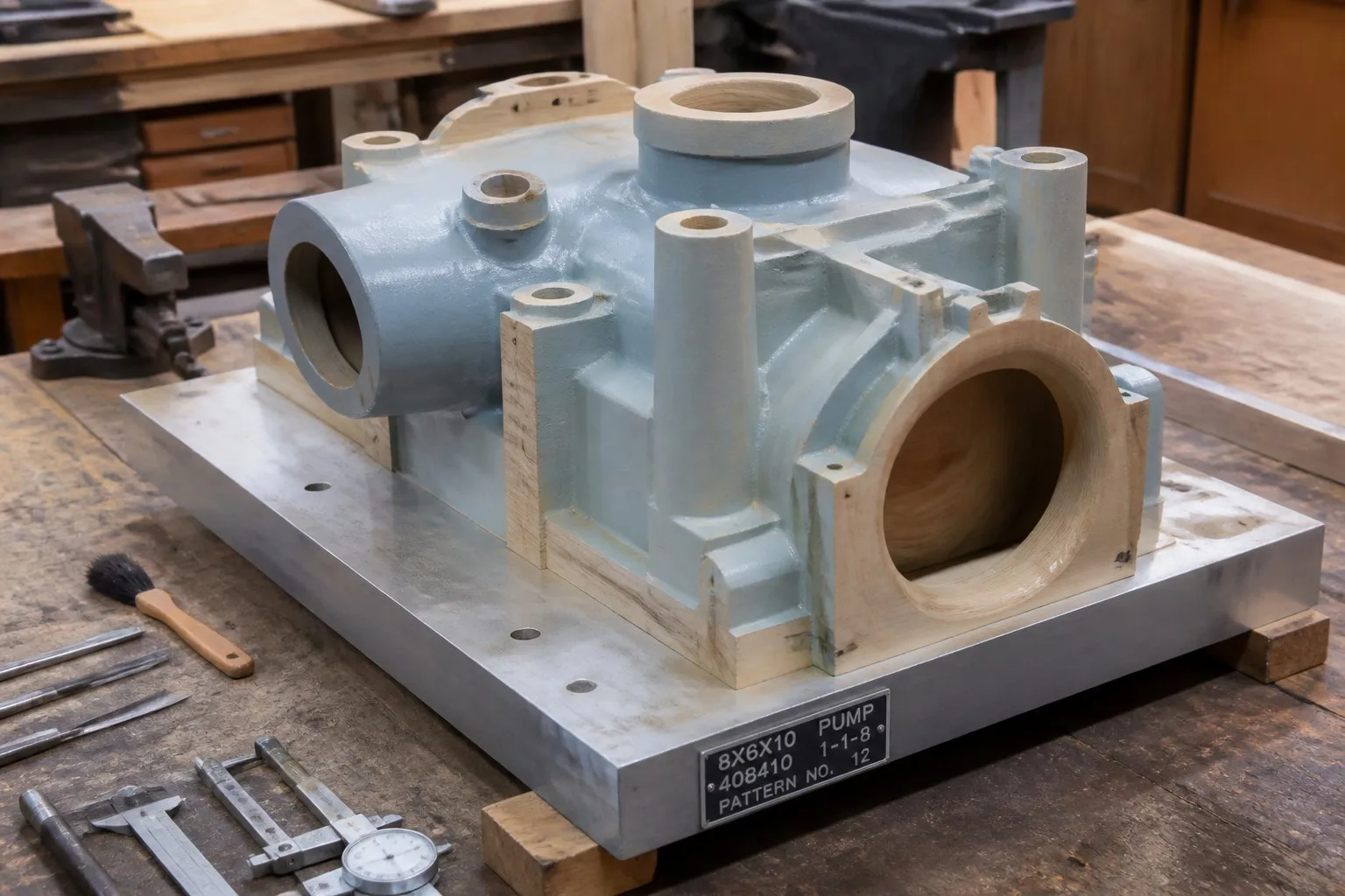
Draft is the taper applied to surfaces parallel to the mold parting direction, enabling the pattern to be withdrawn without damaging the mold cavity.
Draft direction convention: Draft is always applied as added material — the as-cast surface at the parting line defines the nominal dimension, and material is added as the surface recedes from the parting line. This means draft increases casting weight slightly and creates a surface that is not perpendicular to the parting plane — both of which affect the machining strategy.
Machining consequence: Drafted surfaces that are functional (sealing faces, bearing seats, locating features) must be machined to square. The designer must ensure sufficient machining allowance at the small end of the draft (where the cast surface is farthest from the finished surface). A common DFM error is specifying 3 mm machining allowance at the parting line but only achieving 0.5 mm at the draft's far end — insufficient for clean-up.
3. Fillets and Radii: Eliminating Stress Concentrators
Sharp internal corners are the enemy of castings. They act as stress concentrators, hot-spot nucleation sites for shrinkage, and crack initiation points during cooling. Every internal corner must have a radius.