
Blog
Metal Casting Defects: A Complete Guide to Identification, Root Causes,and Prevention
Meta Description: A comprehensive guide to 20+ metal casting defects — organized by category. Learn to identify surface, internal, dimensional, and material defects, understand their root causes, and implement proven prevention strategies for steel and iron castings.
Every foundry produces defective castings. The difference between a world-class foundry and an average one is not the absence of defects — it is the systematic ability to identify defect root causes, implement corrective actions, and prevent recurrence. For buyers and engineers sourcing cast components, understanding casting defects is essential: it enables informed acceptance decisions, realistic quality expectations, and productive collaboration with foundry technical teams.
This guide categorizes more than 20 casting defects into four groups — surface defects, internal defects, dimensional defects, and material defects — and provides for each: visual identification characteristics, root cause analysis, proven prevention methods, and repair feasibility assessment.
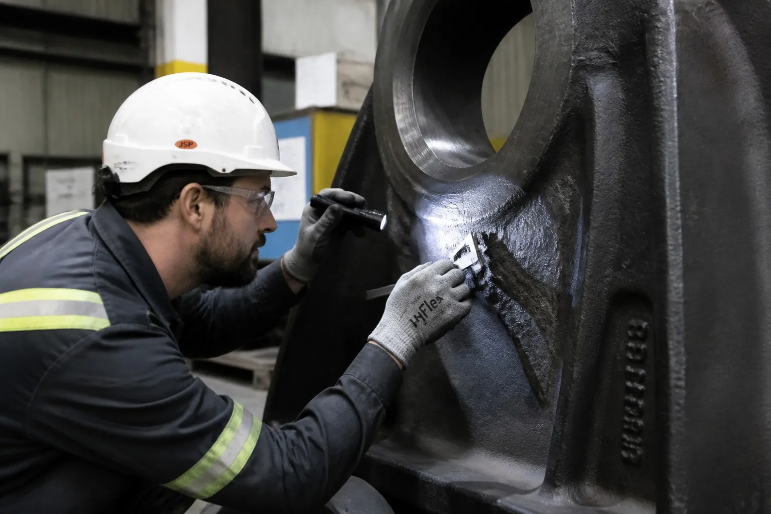
Part 1: Surface Defects
Surface defects are visible on the casting exterior without sectioning or volumetric NDT. They are typically detected by visual inspection (VT), magnetic particle testing (MT), or dye penetrant testing (PT).
1.1 Cracks
Cracks are the most serious category of casting defects — they compromise structural integrity, act as stress concentrators, and can propagate under service loading.
Hot Tears (Hot Cracking)
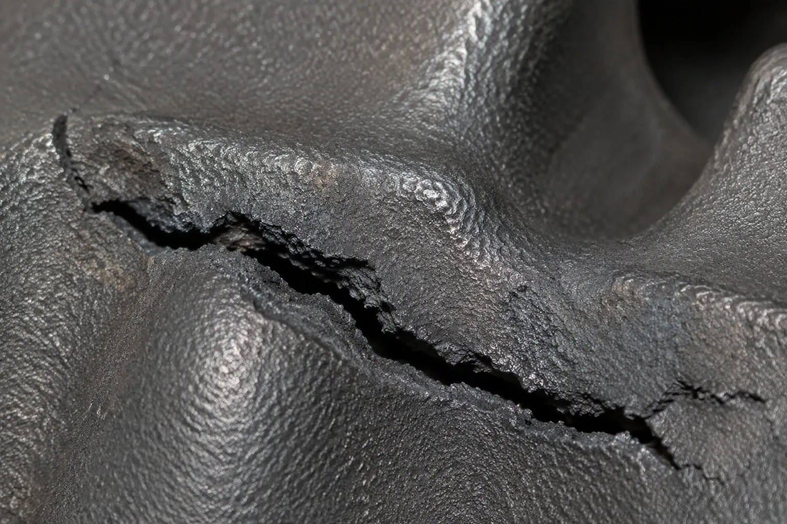
Visual identification: Irregular, jagged, branching cracks with oxidized (dark blue/black) fracture surfaces. Typically occur at section thickness transitions and hot spots. The crack surface shows dendritic morphology, indicating the metal was partially solidified when the fracture occurred.
Root causes:
- Differential cooling rates between thick and thin sections create thermal stresses exceeding the metal's hot strength
- Insufficient mold/core collapsibility — the mold or core resists the casting's natural contraction during cooling
- Poor pattern design with abrupt section transitions and inadequate fillet radii
- Excessive pouring temperature — increases the temperature gradient and thermal stress
- High sulfur or phosphorus content in steel — segregates to grain boundaries and reduces hot ductility
Prevention:
- Design uniform wall thickness; use tapered transitions (≥3:1) between sections of different thickness
- Use collapsible cores and mold materials with good thermal decomposition characteristics
- Add generous fillet radii (≥0.5× wall thickness) at all internal corners
- Control pouring temperature — the minimum temperature that fills the mold completely
- Maintain sulfur below 0.030% and phosphorus below 0.040% for steel castings
- Add chills to accelerate cooling of heavy sections, equalizing cooling rates across the casting
Repair feasibility: Weld-repairable with qualified procedures. Requires complete crack removal by arc gouging or grinding, preheat to 200–350 °C, qualified filler metal, and post-weld heat treatment. Not all applications permit crack repair — check the governing code or specification.
Cold Cracks (Cold Shut Defect)
Visual identification: Narrow, straight cracks with clean (unoxidized), bright fracture surfaces — indicating the crack formed at low temperature after solidification was complete. Often appear at sharp corners, thin sections subjected to residual stress, or areas of high restraint.
Root causes:
- Excessive residual stress from non-uniform cooling — the crack initiates when residual tensile stress exceeds the material's fracture strength at ambient temperature
- Martensite formation in alloy steels quenched too severely — volume expansion during martensitic transformation creates internal stress
- Hydrogen embrittlement — atomic hydrogen dissolved in the steel diffuses to regions of high triaxial stress and causes delayed cracking
- Improper riser removal — impact or thermal shock during riser knock-off initiates cracks
Prevention:
- Stress-relief anneal immediately after shakeout (do not allow castings to cool to ambient before stress relieving)
- Control quenching severity for alloy steels — use oil or polymer quench instead of water
- Bake at 200–250 °C for 2–4 hours per 25 mm of section thickness for hydrogen bake-out (de-embrittlement)
- Use breaker cores at riser contacts to facilitate clean riser separation
- Handle castings carefully during shakeout and fettling — avoid impact loading
Repair feasibility: Weld-repairable if the crack is accessible and the material is weldable (carbon steel, low-alloy steel). Austenitic stainless steels can be repaired. Ductile iron and gray iron cracks are difficult to repair reliably — scrapping is often more economical.
1.2 Cold Shuts
Visual identification: A visible seam or discontinuity on the casting surface where two streams of molten metal met but did not fuse. The defect appears as a smooth-edged groove or crack-like line, often with rounded edges — distinguishing it from a crack, which has sharp edges.
Root causes:
- Pouring temperature too low — metal begins to solidify before the mold is completely filled
- Pouring speed too slow — the metal front cools and oxidizes before the mold fills
- Inadequate gating system design — multiple metal streams arrive at the same location at different temperatures
- Turbulent pouring — metal splashes and cools, forming droplets that do not fuse with the main stream
- Low mold permeability — back pressure from mold gases slows the metal front
Prevention:
- Increase pouring temperature by 20–50 °C
- Optimize gating system to deliver metal to all sections simultaneously at consistent temperature
- Use multiple ingates for large castings; position ingates to avoid long flow paths
- Pour steadily — avoid interrupted or stop-start pouring
- Improve mold venting
Repair feasibility: Cold shuts on non-critical surfaces can be ground out if the depth is within machining allowance. Deep cold shuts are essentially cracks and should be treated as such — weld repair if permitted, otherwise scrap.
1.3 Sand Inclusions
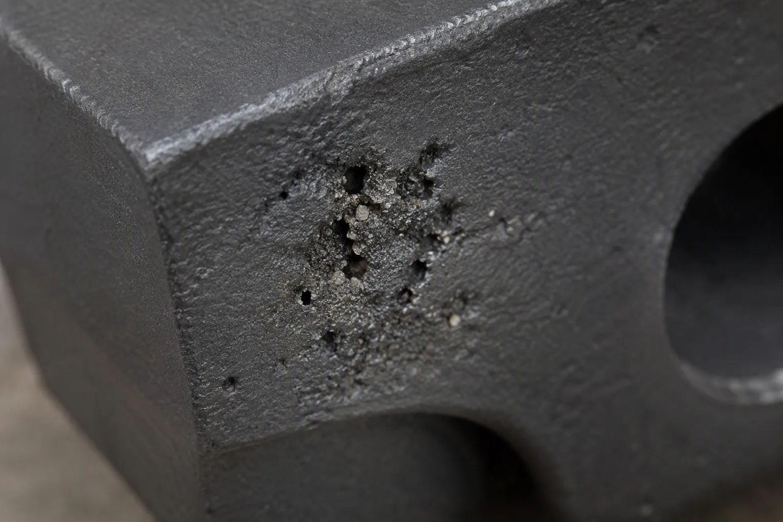
Visual identification: Irregular cavities or depressions on the casting surface partially or completely filled with molding sand. The sand grains are visible within the defect. Often associated with rough, irregular edges.
Root causes:
- Loose sand in the mold cavity not removed before mold closing
- Mold erosion during pouring — the metal stream washes sand from the mold wall
- Insufficient mold strength — the mold surface fails under the metallostatic pressure of the molten metal
- Core breakage during mold assembly or pouring
- Improper gating design — high-velocity metal impingement on mold walls
Prevention:
- Thoroughly clean mold cavities before closing — use compressed air and vacuum
- Design gating system to minimize turbulence and mold wall impingement — use tapered sprue, radiused runner bends, and multiple ingates
- Increase mold strength — use higher clay content, better compaction, or resin-bonded sand
- Apply mold wash (refractory coating) to improve surface strength
- Use ceramic foam filters in the gating system to capture sand and slag particles
Repair feasibility: Surface sand inclusions on machined surfaces are removed during machining (if within the machining allowance). Sand inclusions on as-cast surfaces can be ground out if the resulting depression is acceptable. Deep sand inclusions are not repairable — the casting is scrapped.
1.4 Scabs and Expansion Defects
Visual identification: Raised, rough, flaky patches on the casting surface where a thin layer of metal has separated from the main casting body. Scabs appear as surface crusts partially attached to the casting. Rattails are fine, shallow surface cracks or veins.
Root causes:
- Silica sand expansion — silica undergoes a rapid volume expansion (~5.5%) at 573 °C (alpha-to-beta quartz transformation), causing the mold surface to buckle
- High pouring temperature — intensifies sand expansion
- Insufficient mold permeability — mold gases cannot escape, pressurizing the mold cavity
- Clay-bonded sand with excessive moisture — steam generation causes surface spalling
Prevention:
- Use sand with lower thermal expansion — chromite sand, zircon sand, or silica sand with organic additives that burn out to create expansion buffer space
- Increase clay or binder content to improve hot strength
- Reduce pouring temperature where metallurgically acceptable
- Improve mold venting
- Use mold wash coatings that resist metal penetration
Repair feasibility: Superficial scabs can be ground flush. Scabs that leave depressions exceeding dimensional tolerances generally result in scrapped castings.
1.5 Metal Penetration and Burn-On
Visual identification: Metal or metal oxides penetrating between sand grains at the mold surface, resulting in a rough, sand-impregnated surface. After shot blasting, the surface appears granular with a "sandpaper" texture. Burn-on is a chemical reaction between metal oxides and silica sand forming a strongly adherent layer of iron silicate (fayalite).
Root causes:
- Excessive pouring temperature or metallostatic head — molten metal penetrates between sand grains
- Coarse sand grain size — larger intergranular voids
- Low mold density — inadequate compaction leaves open porosity at the mold surface
- Absence of mold wash — no barrier between metal and sand
- Reactive alloys (high-manganese steels, stainless steels) form low-melting-point silicates that wet the sand surface
Prevention:
- Use finer sand grain size (AFS GFN 50–80 for steel)
- Increase mold compaction
- Apply refractory mold wash (zircon, chromite, or alumina-based for steel; graphite-based for iron)
- Reduce pouring temperature
- For manganese steel and stainless steel: use chromite or zircon facing sand — these are chemically inert and do not react with the molten metal
Repair feasibility: Minor burn-on is removed by extended shot blasting. Heavy metal penetration that leaves surface depressions after cleaning may require grinding — acceptable if dimensions are maintained. Deep penetration is not repairable.
PREVIOUS:Slag Pot Casting: A Complete Engineering Guide to Large Steel Castings for Steel Mills NEXT:Sand Casting vs. Investment Casting vs. Shell Mold Casting: How to Select the Right Process for Your Industrial Components
RELATED NEWS
CATEGORIES
LATEST NEWS
CONTACT US
Name: John Yu
Mobile:+86 15941574876
Tel:+86 15941574876
Whatsapp:+86 15941574876
Email:john_yu@metals-casting.com
Add:Wangjiapu Group, Xinan Village, Qianyang Town, Donggang City, Dandong City, Liaoning Province, China.